1967 Austin Healey Sprite Project
- visualizethis
- Feb 4, 2024
- 1 min read

Welcome to my obsession.
Other than my family, software engineering career, and motorcycling interests, few topics, projects, hobbies, or facets of my life have consumed more of my thoughts over most of my adult life than my love-hate relationship with my 1967 Austin Healey Sprite project. And I'm referring to the day dreams distracting me as far back to the classrooms of my senior year in high school, continuing on through college, and beyond. "Really?!", you might ask. "So shallow. So boring. Is there nothing more to you than that?", another may ponder. Yes, well my life is peppered with all the expected grownup things many get entangled in - college, career, family, home ownership, travel, other interesting hobbies. So yes I have other facets, but this one in particular has been a testament of perseverance and plain stubbornness.
Prehistoric - Prior to 2006
My interest in owning an Austin Healey Sprite originated from stories my dad told about his days serving in the US Army Ski Patrol in Germany between 1953 and 1955. He purchased a 1955 Austin Healey 100-4 there and said it was cheaper to buy abroad and ship back than it was to buy in the States.

Dad's stories spurred my curiosity about the Austin Healey, so my research led me quickly to the Austin Healey 3000 of the sixties. I would occasionally mention how cool it would be to own a newer generation AH with their bigger six cylinder engines. Dad would quickly make me know that he preferred the raspy sound of the 100-4's four cylinder engine. He would reminisce of moments driving up the narrow main street of Pirmasens Germany, reveling in the big four's resonating exhaust sounds as they reflected off the store fronts while cruising by in second gear. In the late 70s, being a cash strapped high school-er, money was too short supply to fund a 'big' Healey, no matter that it was a 3000 or 100-4. I looked for the next best affordable option and that of course became the Austin Healey Sprite. I was biased then to consider only the Sprite and not the MG Midget, even though they are essentially the same car. The Sprite just seem more special to me. I don't know if I even knew at that time that Sprites were less common (therefore more rare) than the Midgets. I think I was just stuck on the "Austin Healey" part of the name as it connected me to my dad's 100-4. So a romance was born for me through this very small entry level sports car and it only intensified when I had my first ride in one. It was 1978, my junior year of high school and I was on the hunt. I scoured the Milwaukee Journal Sentinel Sunday edition want ads for several weeks before I found my target. A 1969 British green Sprite for $500. Now I'll say this, I've owned two Austin Healey Sprites, and the first one - the 69 I just mentioned - was a mistake. It was my first car purchase and one executed by emotion - two powerful influences that would help temper my purchasing decisions of the future. The emotion part made me blind during the test drive. I was the passenger and was enjoying the scent of oil and gas, the rush of wind with the top down, the whine of the straight cut gears, and so glimpsing the road streaming beneath me through the floorboard that was detached from its rocker panel, didn't phase me. I was so excited - what a thrill. Yeah it was a $500 mistake, but only in terms of money wasted on a rust heap. It was nine years old and probably had seen every salty Milwaukee street every Winter since it rolled off the showroom floor. My passion was still stoked by this little rust bucket. It was British and it had "Austin Healey" in the name after all! More importantly, it ran fine, it sounded great, it was a convertible, and handled like a go-kart. I was hooked. Now here is how this flash-in-the-pan purchase was not a mistake. Bad purchase number one, lead me to purchase number two and my final answer. Enter my 1967 Austin Healey Sprite - Signal Red (I'm guessing about the type of red as there were four: Tartan, Damask, Colorado, and Signal. More research is needed here). It's now 1982. My 69 had a good drive train, but it needed body and structural repairs in a bad way, and in a way that I wasn't skilled to provide at the time. So back to the want ads, this time to find a parts donor. The perfect solution presented itself. It was another 69 I found for sale in the town of Monches. This one had a perfect chassis with freshly painted blue body, a blown engine, and torn top. My 69 had the engine and top to complete the equation, plus other good drivetrain components if needed. Another $500 into this and I would have a finished car. Well here's another lesson learned: Don't hesitate if you know what you want and it's staring right at you. I hesitated and the other guy looking at the car at the same time, beat me to the punch. Ooooh, I was not happy. I was very disappointed, but mostly with my indecisiveness. So now what? Fortunately, that "other guy" had driven there in his 1967 Sprite and it looked really nice. It had a bit of typical bonnet nose and A-pillar rust, but was so much better than what I had. It wasn't as good as the marriage of my 69 to the donor would have been, but it was my next best option. The owner must have overheard my plight and reasoning for wanting the donor car, so maybe he felt sorry for me or at least saw the same opportunity and asked if I want to part with my green 69. Still bruised by my recent hesitation, I said yes fairly quickly. I was even quick to express my interest in his 67 as a possible trade (plus some cash of course). How about: $900 + green 69 = $1400. That's what I paid to get my second and final Austin Healey Sprite. The remainder of this blog documents my final push to get it restored along with a short commentary on the lost years of ownership. To spike the interests of those thinking about or currently restoring a Sprite or Midget, my 67 turned out to need pretty much of a complete chassis rebuild. Much time and money might have been spared by cheating and buying a brand new body shell, but then I wouldn't have this wonderful build story to tell. And what fun would that have been anyway. So that being said, there is and will continue to be, a growing library of content here about not only the restoration process but also the tooling up and other preparations one needs when starting such a project from scratch.
The Lost Years of Ownership
I'll make this quick. What happened between the year I acquired my 67 Sprite (1982) and the year I began the appropriately funded and skilled restoration effort (2017), was simply life. Life happened. College, career, motorcycles, marriage, family, home, bicycling, and numerous other distractions. I drove the little car for about a year and a half of the first years of ownership, and then made a poor mans attempt at restoring it while also working on an engineering degree. The attempt fizzled as life took off for me and the car ended up boxed up and put out of sight for years as it bounced between friend's barns and sheds, and then paid storage. I actually gave up on it as my motorcycling and bicycle hobbies consumed my interests. It wasn't until my oldest son was entering high school and my career maturing enough that I found the time and resources to renew my interest in the project. So between the years 2006 and 2017, I built the space, honed my welding and metal working skills, and acquired the necessary tools to begin a serious effort to get this little legend back on the road.
2006-2010 - Tool-shed Construction
A big part of the prep work needed to get the car restoration project off the ground was the need for a dedicated space to operate. The garage therefore needed to be cleansed of anything not car project related. The motorcycle(s), bicycles, lawn and garden equipment all needed a new home. So a two story shed with a 10'x16' footprint was devised. This project is detailed in a separate blog. Please refer to blog: "Project Toolshed Build" for details.
2012-2017 - Tooling Up for a Committed Go At It
...coming soon..
2017 - Front Sub-frame Reconstruction
...coming soon..
2017 - Foot-well, Toe Board, and Inner Rocker Panel Repair
...coming soon..
2018 - Sub-frame Closure Modification
...coming soon..
2019 - Heel Board Reconstruction
...coming soon..
2019-2020 - Floor-pan Replacement
...coming soon..
2020 - Front Inner Wing Repair
...coming soon..
2020 - Chassis Alignment Checks
...coming soon..
2021 - Front Cowl Repair
...coming soon..
2021 - Outer Rocker Panel Repair
...coming soon..
2021 - A-Pillar and Cowling Repair
...coming soon..
2022 - New Rear Rotisserie Mounts
To prepare for the restoration work of the boot floor-pan, inner wheel wells, and quarter panels, I needed to reposition the rear rotisserie hoop forward to improve access. The mount I replaced was attached to the car via the rear mounting points for the leaf springs. It essentially attached to the boot floor-pan and supporting subframe. The new mounts will move the hoop forward to the spring box supports - the mounting points for the front of the leaf springs. This would provide all the access I need to finish the last phase of the metal work. It will also serve as the final rotisserie configuration that will be used during media blasting, priming, and seam sealing.
The images below show the initial fitting, tack and fillet welding, and final positioning of the new mounts to the spring boxes.


Here are photos of the rear rotisserie hoop in its new position and shows the new found access I'll have to begin work on the boot.


The struts tying the rear hoop to the rotisserie main frame serve only to keep the hoops parallel and prevent angular movement of the hoops that would stress the mounting points on the car. These struts had to be shortened to accommodate the new home for the repositioned hoop.


2022 - Boot Floor-pan Replacement - Part 1
Repairing rot in the boot floor-pan and adjacent flanges can be performed a number of different ways depending on the severity of the damage. If the rot is minor and typically near the spot welded joins, those sections can be cut out and patched in piecemeal fashion. If many such repairs are needed then it is probably better to go with one of two of the replacement panels available. There is the rear most section available that requires a cut at the top of the axle mound or there is the complete factory panel available to replace the entire floor. Considering the access holes I had to cut to gain access for repairing the heal board, I chose to purchase the entire floor-pan with a Heritage supplied panel.
This being the first time doing such a large repair that had so many off plane mounting points (unlike the floor pan which was basically a single plane fitting), I had my doubts as to whether I could actually fit the whole panel in place without cutting or bending it. I found no help on-line as all the examples I found were either piecemeal section repairs or just the rear half boot panel replacement.
The first step was to remove the old boot floor-pan and clean up all the mounting flanges so that I could attempt to place the new pan in position.


In the process of cleaning up the mounting flanges, I carefully removed the mounting flange for the bump stop (below). I would need this piece later to serve as a template to fabricate a new one.


With the flanges clear of the old pieces, the moment of truth had arrived. Time to try the first fitting of the new boot floor-pan. As the following images show, I found it easier to rotate the car to a near vertical position to facilitate in getting the new and somewhat heavy panel in position. After getting the flange near the heal board tucked in first and with a little bending of the flanges surrounding the wheel wells, I did manage to make it fit.


The next step was to gain access to all mating flanges and check for fit and any flanges that needed to be repaired. As the following images show, I decided to cut out an access hole into the rear section of the quarter panels. I left enough material in place to keep the whole structure well supported. And yes, I already had new Heritage quarter panels in my parts supply.


The one area where I initially struggled to get the floor-pan to mate was where it joins with the rear sub-frame mounting flanges. As the images below show, there was a considerable gap that had to be closed in order to obtain a tight fit for welding. I used the weight of the car with rotisserie attached and jack stands to help lessen the gap. I planned on eventually using sheet metal screws to finalize the fit.


The following images show the cancer that affected the lower joins of the struts tying the wheel well arches to the boot floor-pan. This is an area where moisture would settle and do its damage. The repair strategy was to cut at a point where only sound metal remained but also allowed for the easiest patch fabrication and join access. The cut out piece served well as a template for the new 20 gauge patch.


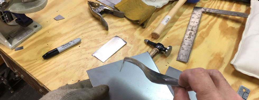
The following images show use of sheer, shrinker, body hammer, and custom dolly to form the new patch panel. This piece entailed some challenging fabrication elements. The shrinker was needed to help draw in the 90 degree edge folds that were on a curve.


I then tested the patch fit to check edge alignment so I could gauge where to start forming the stepped edge of the triangular hole as seen below. This probably would be best performed with a bead roller that I don't have. I settled instead by using a pick hammer and a vise mounted custom dolly to help shape the step. It looked a little rough at first pass, but with continued coaxing it improved to the point of 100% good enough.


The following images show the final fitting prior to welding. I butt welded from the back side to minimize the grinding needed for presentation. Lastly, a section of the patch needed to be plug welded to emulate the original spot welded join.


2023 - Front Right Inner Wing Repair
I've been avoiding this particular repair as I find it tedious and less of a priority than some of the bigger repairs on my list. Having just completed the boot floor replacement, I'm looking for something a little smaller to tackle. Also having performed the same repair on the driver side inner wheel well in 2018, I am better equipped to tackle it without all the mental hoopla.
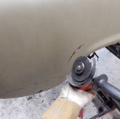
As the two photos below show, there is considerable rust between layers that is evident with the swelling and rust through. First order of business is to trace what needs to be cut out. I bore two large holes (seen at the top of the traced trapezoid) to prevent sharp corners for the patch weld. Unfortunately the 14 gauge reinforcement plate behind what you see below needs to be removed to gain access to repair inner fender and structural A-frame flange it attaches too.


The following five photos show the 14 gauge reinforcement plate that needs to be removed to gain access to the inner fender repair section. To expose the spot welds to drill, I used a sanding block to reveal them quite effectively as seen in the first photo. Using my trusty Harbor Freight spot weld cutters and chisel, I free the spot welded portion but need to cut/grind the seam welds anchoring the plate to the spring tower. With the plate removed one can see where moisture got trapped between the layers and did its damage.


The following images show the rotted section getting cut out and surrounding flanges corrected. Note that I got lucky in that I didn't need to cut out any of the complicated curvy and folded leading edge. I had to do so on the driver side repair and that required a bit more fabrication to correct.


The following images show me making a template to translate to a 20 gauge sheet to trace out a patch. Following this with tack, butt welding, and grinding.


Next up I needed to make a reinforcement panel to replace the one I had to destroy to get at the underlying rust. I used the original panel to make a template for my plasma cutter. The template was then clamped onto a fresh 14 gauge sheet to serve as a guide to cut a new one.


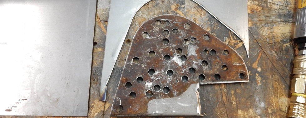


The new reinforcement panel blank then needed a notch cut out and strengthening lip bent on to its forward edge. I used my press to bend the 90 degree lip and cutoff disk to cut and shape the notch to fit and mate up with the car for welding.


The images below show the plug weld holes and rust proofing with zinc weld through primer on the new reinforcement panel. I let the primer dry for at least a half hour. Then I clamp the panel in place and use my scraper bit to clean the primer out of the plug weld holes to prep for welding.
Typically when plug welding, I set the welder one or two setting hotter than the base metal thickness requires for a seam weld, start in the center and spiral outward to fuse the top layer. The trick is go in hot and fast. This situation was a little different since the top layer was much thicker than the base metal. What I did in this case was set my welder to handle the 14 gauge top layer and started the plug welds on the edge of the hole spiraling inward. A few dozen plug welds and one seam weld later the panel is in place and ready for grinding.


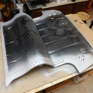
Sometimes it is easier to replace an entire panel rather than patching it. That's what I did for both inner fender panels. Each of these had most of their corrosion trapped between the layers of spot welded metal and was evident by the swelling adjacent to the welds. Using my Harbor Freight spot weld cutter I made quick removal of the old panel. Using the old as a template, it was pretty straight forward to fabricate a new one. The following images show the new panel with plug weld holes drilled and zinc weld through primer applied.


Next I clamped the new panel to the car along with the outer wheel well lip, checked for proper fit, and cleaned out the primer from the holes to prep for welding. I welded from the bottom side where it was convenient to hide and minimize grinding needed since the undersides would be less visible than the top sides that I would always see when the bonnet was open.


Though this was a simple panel to fabricate, there were a good number of plug welds required to fuse it to the car. Note in the last image below the folded front edge of the panel. I used my press to start the fold and then hammer and dolly to finish it. I also made sure there was adequate zinc primer trapped in the seam to help fight future corrosion.


The lower portions of the inner fenders where they meet up with the rocker panels had rot that I needed to cut out and weld in patches. This can be seen in the following images.


The last detail was to weld in a replacement wire harness holding tab. The finished repair is shown as follows.


2023 - Rear Sub-frame Alignment
There were a number of telltale signs showing that my car, while under previous ownership, had suffered a minor rear end collision. The hit was to the passenger side tail lamp area. The evidence is four fold: 1) the wheel well to boot floor-pan strengthening strut was obviously straightened as crumpling and creases were present, 2) the passenger side leaf spring rear to front mount distance measures 1/4" shorter, 3) my chassis measurements showed that the rear leaf spring mount was pushed a 1/4" down compared to its sibling, and 4) the top of the passenger side B-pillar got pushed outward by a 1/4" roughly. The B-pillar damage manifested itself by poor door alignment and a crease present in the inside pressing that ties the B-pillar to the wheel arch.
I decided to fix these offsets in two stages. First I would stretch the rear spring mount backward and upward a 1/4" in one motion using a Harbor Freight variant of a 4-ton Porta-Power hydraulic press. Secondly I would push in the B-pillar by hand later on when I had removed the old quarter panel, thus weakening that area enough to easily manipulate it.
I fabricated a plate with a catch that would bolt to the leaf spring mount and capture the business end of the ram. The base of the press would work against the well supported heal board. This arrangement is shown in the following images.


To gauge the stretch progress, I positioned the pointer of my tram-gauge to just touch a bolt on the leaf spring mount. The second image below shows some slicing I did to relieve the quarter panel and inner wheel well from fighting back. There was a bit of expected spring back, but pushing a bit beyond the target point was all that was needed.


The following image shows the final position of the tram-gauge pointer after the stretch. The pointer started in the center of the bolt head shown. I made a mental note to keep track of this measure to ensure that it would stay in place at the time that I would weld up the inner wheel arches and quarter panel.

2023 - Boot Floor-pan Replacement - Part 2


2023 - Bump-stop and Shock Support Replacement


2023 - Rear Right Valance Patch Build


2023 - Rear Right Quarter Pane


Comments